Learning Objectives
- Understand the application and installation of strap braced shear walls in light gauge steel building construction
- Review the design requirements of strap braced walls in AISI standards and ASCE 7 minimum loads
Buildings need lateral load resisting system to provide lateral stiffness and to transfer acting shear loads from wind or seismic forces down to the foundation. Buildings with sufficient lateral stiffness will suffer less non-structural damage, which means less cracking in walls and finishes, less water infiltration, and increased durability. Diagonal strap braced walls eliminate the need for plywood, OSB, or steel sheet sheathed shear panels, all of which require excessive and complex fastener schedules. They have been effectively used in residential and commercial low and mid-rise cold-formed steel applications.
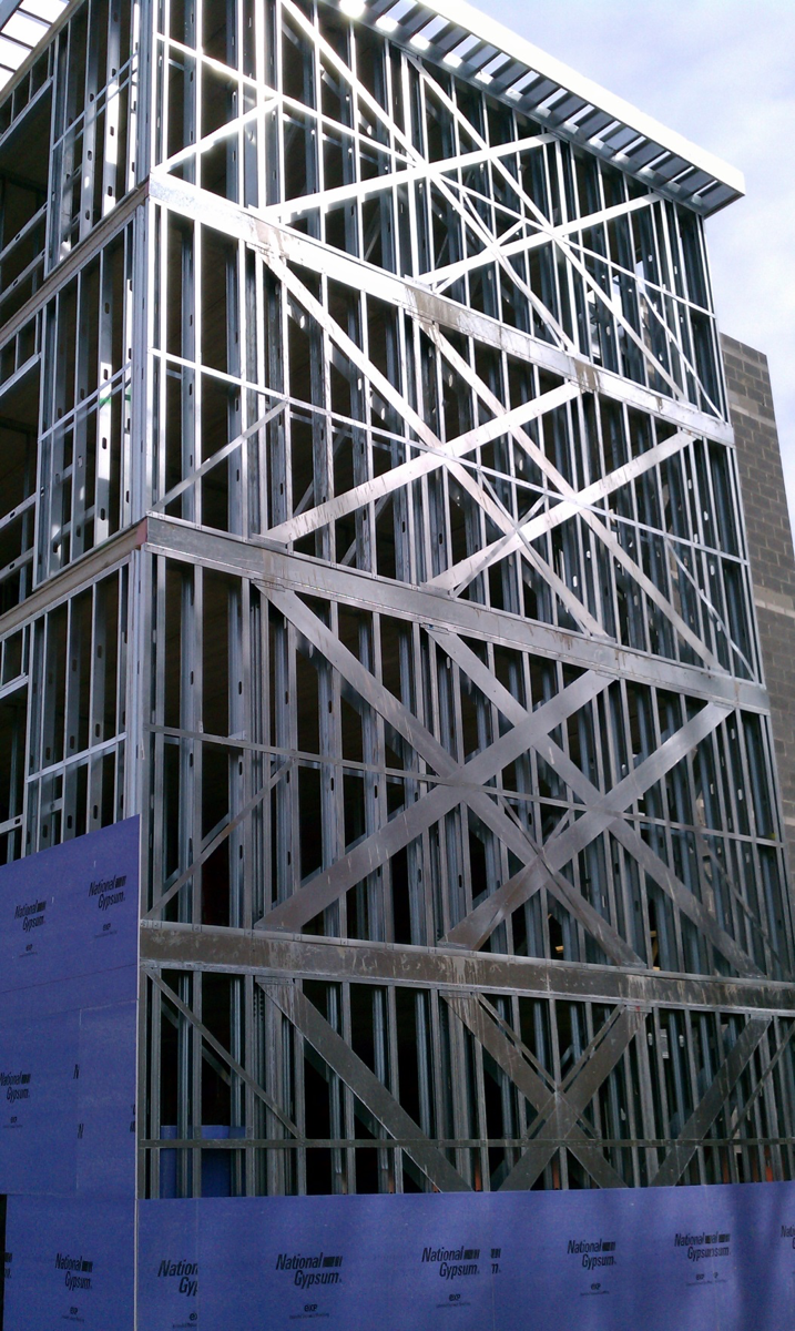
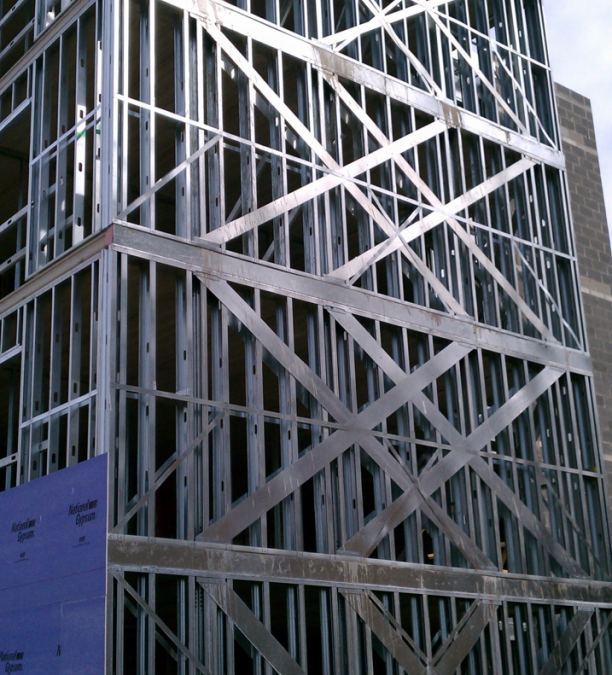
Stacked Strap Braced Shear Walls
Strap braced walls should be designed according to the North American Specification for the Design of Cold-Formed Steel Structural Members (AISI S100) and the North American Standard for Cold-formed Steel Framing – Lateral Design (AISI S213). Section C4 of the AISI S213 standard limits the aspect ratio (height/width) of a shear wall with diagonal strap bracing to not exceeding 2:1 unless a rational analysis is performed which includes joint flexibility and end moments in the design of the end chord Columns.
It is generally recommended to keep the range of wall aspect ratio between 0.6 and 2 for simplicity of construction and to avoid the additional analysis with chord end moment. Strap braced walls are typically analyzed as a truss model with lateral and/or gravity loads applied at joints that represent the points of contact between the shear wall and the floor/roof diaphragms. Load should be factored based on the design method selected for analysis (strength design or allowable stress design) and proper load combinations should be applied per ASCE Standard for Minimum Design Loads for Buildings and Other Structures (ASCE 7-10). In any shear wall panel, only diagonal bracing acting in tension should be modeled since strap bracing is not capable of resisting compression forces.
When strap braced walls are designed to resist lateral seismic forces, the seismic loads are to be calculated based on a seismic response modification coefficient, R = 4, as recommended in Chapter 12 of the ASCE 7-10 standard. However, attention should be given to Sections C1.1 and C5.2 in the AISI S213 standard for the consideration of special seismic requirements in the design when R is taken greater than 3. Further clarification for the use of special seismic design is given Section C1.1 of AISI S213 standard. The clarification states that for Seismic Design Category A through C, the designer has the option to use an R = 3 (instead of 4) to determine the seismic loads and thereby avoid the special detailing in Section C5.2. In Seismic Design Category D through F, the designer must use R = 4 and must apply special detailing in Section C5.2.
Diagonal straps in strap braced walls must be installed tight to ensure the shear wall panel will perform as designed. It is recommended to tighten the straps in the field after the application of gravity loads on floor where shear wall panels exist. In the case of panelized walls in the fabrication shop, it is recommended to compress the panels in a jig before the straps are tightened and secured. Diagonal straps cannot be installed, then un-installed by releasing the end screws, and then re-installed with screws again in the same screw holes. Either a new piece of strap is required, or the exposed edge of the strap to be welded with an approved weld design. It is not recommended to fasten the diagonal straps to the intermediate studs between the end chords. However, the typical or occasional attachment of sheathing and/or resilient channel to the intermediate studs through the straps is acceptable. Finally, diagonal straps are major elements in the lateral load resistance of the building, and therefore the straps should not be cut, punched or spliced without an approved design.
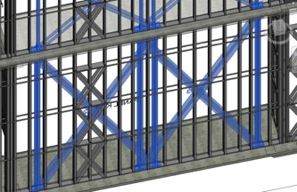
3D BIM Model for Strap Braced Walls
FDR Engineers specify strap braced shear walls when they are best suited in light steel framing applications. They provide detailed shop and fabrication drawings as well as 3D BIM modeling and installer guidelines to make sure fabrication and installation are completed to the intent of design. This simply saves time and effort for FDR’s clients, and ensures the building is safely designed and erected.

Recent Comments